Time to go autonomous.
Growing tired of swamp cooling for fermentation “temperature control” I’ve decided it’s time to invest in the widely popular 2-stage STC-1000 “ebay” temperature controller. And with a spare mini-fridge from college simply sitting in the detached garage- why not, right? This project in it’s entirety was inspired by the HomeBrewTalk.com community and countless user write-ups with similar projects (hey- credit where credit is due). So let’s build this damn thing! Here’s what you’ll need:
Parts List:
- QTY 1 – STC-1000 Digital Temperature Controller ($19.99 Ebay)
- QTY 1 – 120V Alpinetech 22mm Blue LED Indicator Light ($4.95 Ebay)
- QTY 1 – 120V Alpinetech 22mm Red LED Indicator Light ($4.95 Ebay)
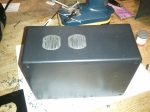
- QTY 1 – 7″ x 5″ x 3″ Project Box ($7.49 RadioShack)
- QTY 1 – 10′-0″ 14 gauge replacement power cord ($13.97 Lowe’s)
- QTY 1 – 115V-1Phase-15A Black Receptacle ($1.99 Lowe’s)
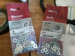
- QTY 1 – Bag of 6/32 Nuts ($1.18 Lowe’s)
- QTY 1 – Bag of SAE No. 6 flat washers ($1.18 Lowe’s)
- QTY 1 – Black Outlet cover ($0.39 Lowe’s)
Tools List:
- Wire strippers/cutters
- Screw driver
- Dremel (or other cutting tool)
- Power Drill
- Step Bit
- Needle nose pliers
- Voltmeter
Total Cost $56.09
Depending what you have in your garage- you may need to purchase additional incidentals such as wire-nuts ($2.58/bag), Dremel cutting tools ($6.18/cylinder), etc., etc. however I’ve excluded these items from the above parts list as most DIY-ers will already have these items on hand.
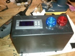
The LED indicator lights are completely optional. The reason I (and many others) choose to include indicator lights is to have a clear visual display communicating whether the controller is calling for either cooling (blue) or heating (red). These 120V LED lights from Alpinetech are truly a perfect fit- small enough to fit into a project box yet big/bright enough to see from across the room, affordable (at $4.95/each), and most importantly.. the correct voltage (120V/1Phase) for this application. But it is a place to shave off $9.90 +S/H from your bottom line- just sayin’.
Step #1 Time to get into the weeds; the wiring diagram.

So… If you are now lost… STOP! And- to be fair… I’m also not an electrician and electricity is extremely dangerous. Consult a certified and-or licensed electrician to check your work if in doubt. This write up is a guide (and not the gospel). Do not risk your life to save money as there are several commercially available pre-assembled temperature controllers in today’s marketplace.
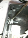
Step #2 Break the bridge.


A very important step in the above wiring diagram is to break the bridge (-or tab) connecting the two hot terminals on the receptacle. By doing so- it allows each outlet to be positively charged independently from one another. -Or for this project- it allows you to have one outlet for cooling and one outlet for heating. I was able to remove the bridge with neelde nose plyers and a little “persuasion” as shown in the above images. No need to remove the bridge on the neutral side as the receptacles can still share a common neutral connection thus reducing the number of wires needed. (See- saving both time & money already!)
Step #3 Templates are amazing.
Once you’ve figured out how you want the finished controller assembly to look create a template(s) (and make copies). A simple template will save time and limit ones frustration while cutting out the openings in the project box. Hey -it’s not brain surgery- but a little precision never hurt anybody.


Step #5 Let er’ rip!
Begin cutting out the required openings. Remember- a hole can always get larger… however making a hole smaller requires a magician. Cut conservatively.

-

- Use Step Bit for indicator lights.

-

- The receptacle openings aren’t “totally” round. Use Dremel for receptacle openings.
Step #6 Confirm opening sizes. Repeat Step #5 as necessary.

Step #7 Drill a hole for the power cable & temperature probe. Time to begin the wiring process.
Now that you’re an expert cutting openings in the project box using either a large drill bit or a step-bit cut a hole(s) for both the power cable & temperature probe. No need for a template here as you are now an expert project box surgeon- remember?


Step #8 Moment of truth…
Well it looks the part… now it’s time to test out your wiring skills… This is also a great time to confirm both outlets are truly operating independently. When “cooling” is activated- the receptacle wired for “cooling” should read ~120V and the “heating” receptacle should read 0V. The reverse is true while in heating. The below screenshots should help illustrate this test.
-

- In “Cooling” Mode.
-

- In “Heating” Mode.
-

- ~120V for active charged receptacle.
-
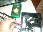
- 0V for inactive receptacle. Success!
Step #9 Close the project box and have a victory brew.
It also helps to have a Celsius to Fahrenheit conversion table. I found mine via our friends at homebrewtalk.com:


Lessons learned? -Of course.
1) The screws to secure the receptacle to the exterior wall of the project box simply weren’t holding under the pressure of plugging/unplugging power cords. A quick fix was to use #6 flat washers & #6-32 hex nuts to keep the receptacle mounted in it’s proper place.
2) Was cooling the left -or the right receptacle? Label them to save yourself the headache of tracing your bird nest of wires.

Now time to build the fermentation chamber 🙂
-Cheers

Just wondering how it worked? No smoke and/or flames? Just wondering cause I have all the bits and pieces and am real close to assembling an almost identical controller myself. Thanks for the detailed description and diagram!
This always seems to be the first question asked..
But in all seriousness- it’s working- and working well. In-fact I have a Black Lager currently fermenting at 50F :). The logic is there- just take time with the wiring. With everything in life, it’s all about the execution of a plan (i.e. make sure you don’t unintentionally short any wires).
Side note– the blue Alpinetech indicator LED light has stopped working. I’ve reached out to the manufacturer to see if they will send a replacement. TBD. Did you go with Alpinetech for your indicator lights -or try someone else?
-cheers
Update: Alpinetech sent a replacement LED at no cost. Buy with confidence; A+.
Glad to hear it’s working well. I looked at a ton of different diagrams/plans on homebrewtalk.com and yours, hands down, is the easiest to decipher. Will be duplicating to a “T”…including the Alpentech lights…ordered mine from Amazon. Should be here in a couple days! Thanks again…
How did your build go?
Just started working on it tonight…got the project box cut out…next step, hard wiring! Does it matter which post the hot/neutral wires connect to on the LED lamps?
The model LEDs I received (as I’ve come to learn.. Alpinetech sends out various models based off their current inventory) there are no indicators suggesting that either terminal is hot/neutral specific. My LEDs function with either terminal acting as the hot or neutral. To be 100% sure- I’d reach out to the manufacturer to ensure the exact components you were shipped are also interchangeable between hot/neutral. Hope this helps!
This is by far the best instructional on how to build a temp controller. Well done. I will be constructing one just like yours. I am curious if you are working on the chamber yet? I’d definitely like to see your project.
Just wired it up yesterday…worked great! Love the LED lamps, a very cool addition. I also added a strain-relief fitting on the back for the power cord and temp sensor…now they are secure, nice and snug.
One last question though…didn’t give it much thought at the time, but I used 16GA wire instead of 14GA. Just did a bunch of reading on different forums, and most guys went with 14GA. I imagine the functionality/safety of the 16GA will depend on how much amperage my chest freezer draws? Think I might run back to Lowes and pick up a new cord, just to be safe. Guess I’ll spend tonight in the garage re-wiring the whole outfit. Lessons learned? Should of used appropriate GA wire the first time…and be careful while cutting out the project box! Somehow the hole for the STC-1000 ended up too big. It still feels secure, just looks a little sloppy.
Thanks again for the excellent plans!
On second thought, and closer inspection, I might stick with the 16GA and add an inline 10A fuse (as a safeguard) on the incoming hot wire. Just checked the freezer and the info panel clearly states 5.0A…so I think I feel fairly comfortable with the current 16GA build.
As I understand it.. required wire gauge is a function of amp draw and linear distance the current needs to travel. I found myself at the same crossroads and opted to go the conservative 14GA route. Here is a handy calculator I found, can’t speak to it’s credibility, but you could use it as a back check:
http://www.gorhamschaffler.com/wire_size_calculator.html
Regardless whether you decide to increase the wire gauge or not- the inline fuse is a great addition.
-cheers
Got it, thanks. Had I done just a tad more research before I wired up the box, I probably would have gone with 14GA like yourself, just to play it extra safe. At this point, going to leave it as-is with the 16GA. Actually fired it up tonight with my paint can heater in the chest freezer…worked like a charm. Peaked my head in the garage and could see that bright red LED glowing from clear across the shop!
How do the LEDs attach into the project box? I’m in the middle of building my own, and thought the LED idea was cool so I ordered some from eBay. Is it threaded or something?
You got it. The Alpine Tech LED housing has a “male” threaded end and a “female” bushing to hold the LED in the project box.
Great writeup! I just built one almost totally to yours, only have the leds on each side of the unit. Two questions for you:
What do you have your differential and compressor wait time set to?
Also if you were to build a new unit at some point would you consider adding an inline fuse?
Brian- great questions. My compressor delay time is set to 2 minutes and yes I would most likely add an inline fuse for added safety/back-up.
Were you guys using braided 14 gauge wire? or 14 gauge solid copper? I was just tinkering with my setup and the solid copper wire is too damn strong.
Solid copper for the wire I picked up at the local home improvement store. Agreed, it’s not the easiest to work with. Where would you find braided electrical wire?
Great writeup and excellent wiring graphic, it was very helpful. I followed your design except I used the Inkbird ITC-1000, which is about the same price and supports F or C. Also I’m using Wago push-wire connectors instead of wire nuts. So far no sparking or smoking. Hopefully in a few months I’ll be able to enjoy a well-lagered Maibock.
This is a great write up on the build. I used your plans to build mine the other day.
One change I made, instead of cutting out each socket and mounting the wall outlet from inside I just cut a big hole that would allow the outlet to install from the outside. Simply slip the outlet into the hole from the outside of the box and drill a small hole for mounting screws. The outlet cover fits better and hides everything nicely and it’s secure without needing the washers and nuts.
Thanks for the inspiration and wiring diagram guidance! I built mine based on your design but with a few differences.
Same box but mounted the STC-1000 on the short end.
Used smaller Alpinetech LEDs
Used an outlet that had push connectors and screws so I used them to minimize the use of wire nuts (used 3 wire nuts total)
Used a detachable computer cable/plug for box power
Mounted an always-on outlet on the side
Have a temp probe with a headphone jack type connection that is mounted on the back of the box.
This was my first attempt at cutting a box, so I knew it was going to be a bit of a hack job. You can see in the photos where I learned that my Dremel was rubbing the box a little too late in the process. Oh well.
FWIW, I used a Dremel cutting wheel and router bit in making the box. I also used a sanding drum to sand down the ridges inside the box so some things would mount flush against the inside. I also used 14 AWG wire.
https://goo.gl/photos/xfMunL5gsozM1WXT7